Overview
Arduino UNO R4 WiFi doesn’t have EEPROM memory, per the microcontroller’s datasheet it has flash memory of size 8kB with 100,000 program/erase (P/E) cycles. On Arduino UNO R4 series, the flash memory is emulated as EEPROM for library functions compatibility. In this lecture, you will learn to create an example project which makes use of EEPROM (Electrically Erasable Programmable Read-Only Memory) memory on Arduino UNO R4 WiFi board.
Downside of using Flash as emulated EEPROM
There are downsides to using Flash memory as emulated EEPROM:
- To write a byte, an entire unit must be erased first, sequence of operations include: reading the entire unit, modifying the byte in a buffer, erasing the unit, and rewriting all bytes. That is total of 1 read op, 1 erase op and 1 write operation for writing a single byte on flash memory. That’s expensive, these counts will explode quickly if you are writing 100’s of bytes.
- This results in potential overuse of EEPROM cycles, especially in scenarios like continuously writing with changing inputs (e.g., analog readings).
- For data logging, the EEPROM library is inefficient and may cause premature wear of the EEPROM.
You should use the emulated EEPROM memory on Arduino R4 WiFi in the case if your application requires less writes and memory wise your application requires limited number of bytes, that will prevent flash memory from wearing out.
Design concept when using non-volatile memory like EEPROM
Use the following steps when designing software that makes use of EEPROM or any type of non-volatile memory:
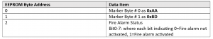
- Use a spreadsheet to map out amount of bytes required for data items that you would like to store on EEPROM.
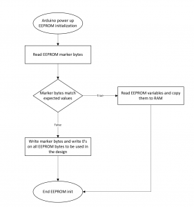
- Have marker bytes on EEPROM indicating valid information on it.
- Upon system powerup, go through initialization process, read EEPROM, if it has valid marker bytes, then read EEPROM saved information to RAM memory where necessary, if it doesn’t have marker bytes, initialize EEPROM memory and write marker bytes on it.
Example project
Design software to detect fire/smoke sensor inputs (D0 – D7 digital input pins) and set an fire alarm status for alarm activation when that happens. In addition, make sure system is able to retain the fire alarm status in the case of power outage or power cycles. Once fire alarm status is set, a reset (via D8 digital input pin) shall be required to reset the fire alarm status.
Source code: